KillerDAC

I mentioned something about my primary DAC in a previous blog article (UpTone JS-2). This article describes in more detail how this unique, one-of-a-kind DAC come to be - an origin story! The KillerDAC is an old school DAC:
- DAC chip is a 16 bit TDA1541A S2 double crown (Taiwan) chip
- Tube rectifier (1x 5U4G)
- Valve output stage (2x 6DJ8/ECC88)
- I2S and S/PDIF inputs
The KillerDAC cannot decode DSD, nor can it play anything higher than 96 kHz/24 bits. This is old school red book DAC, and it sounds amazing to my ears. A device with no fancy marketing gimmicks, and it's role is to solely playback beautiful music that can touch my soul.
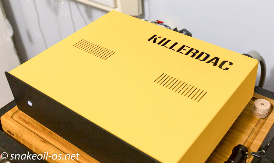
Here it is in it's current form:
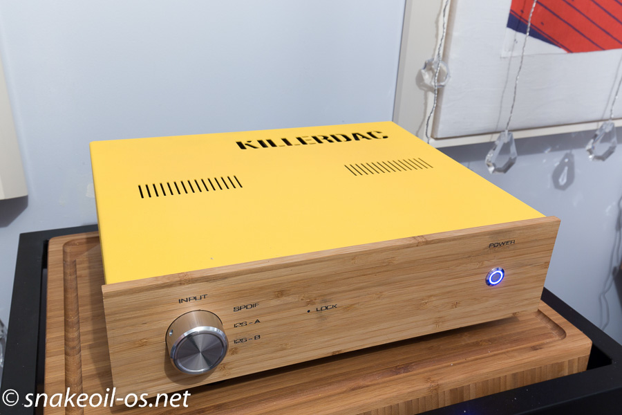
And to my eyes it looks stunning in the looks department too. But it didn't start off like this.
This DAC was in a pretty poor condition when I purchased it second hand. It required a lot of work, a local Perth audiophile (Doncentric) offered his help fix it all up. And thus begins the amazing journey.
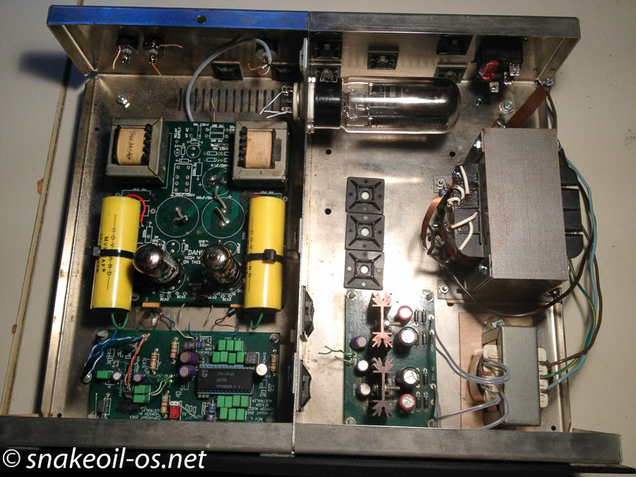
Don works and thinks at a very fast pace, and he he has that uncanny ability to maintain focus and pay attention to the tiny details. This is the state of the machine when I first got it . Some caps and wires (dried out and brittle CAT5 Ethernet cable) have already been snipped.
I never kept a picture of the DAC in it's original case as it looks ugly - just a simple black box. You can see the case cover as you read on. Bottom left is the DAC board, the previous owner stripped Ethernet cables and use that as hook up cables. While it is good (Teflon is a good thing), the wires are solid core and it presents no ends of problems.
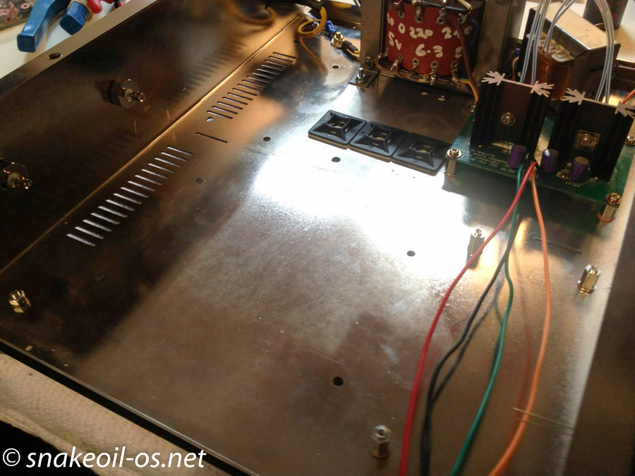
First thing Don did is to clean the case up! The case has certainly seen better days.

Hiding beneath the fingerprint marks, grime, grease and oil is a beautiful shine, and how pretty it looks when cleaned up. Here you see a partial reassembly of the power supply.
A top down view, here you can see the ugly black aluminum fascia. The spacer nut is a special component sourced from Singapore - it has a ring that allows secure seating of the PCB. A power switch was added for convenience.

This is the noise divider, and also where the tube rectifier is mounted (in a horizontal configuration). Don added grommets to protect the wires passing through.

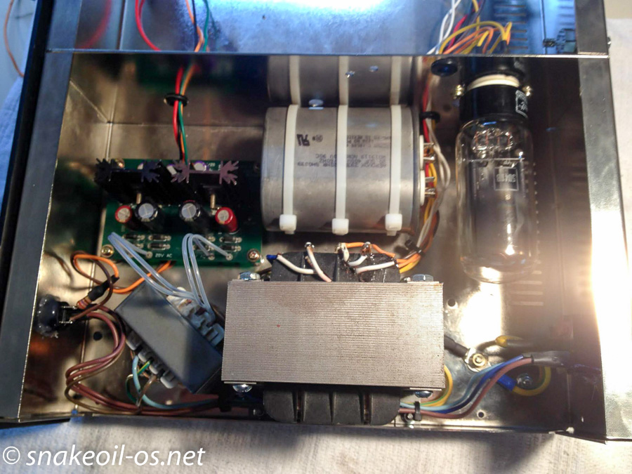
This picture shows the finished power supply section, with the divider fitted back into it's place, and the hot 5U4G rectifier tube.
This next picture shows the back of the KillerDAC, the two solder free RCA sockets you see of the left are the analogue outs, while the single S/PDIF on the right (right next to the high voltage tube socket |-|) is the S/PDIF input.

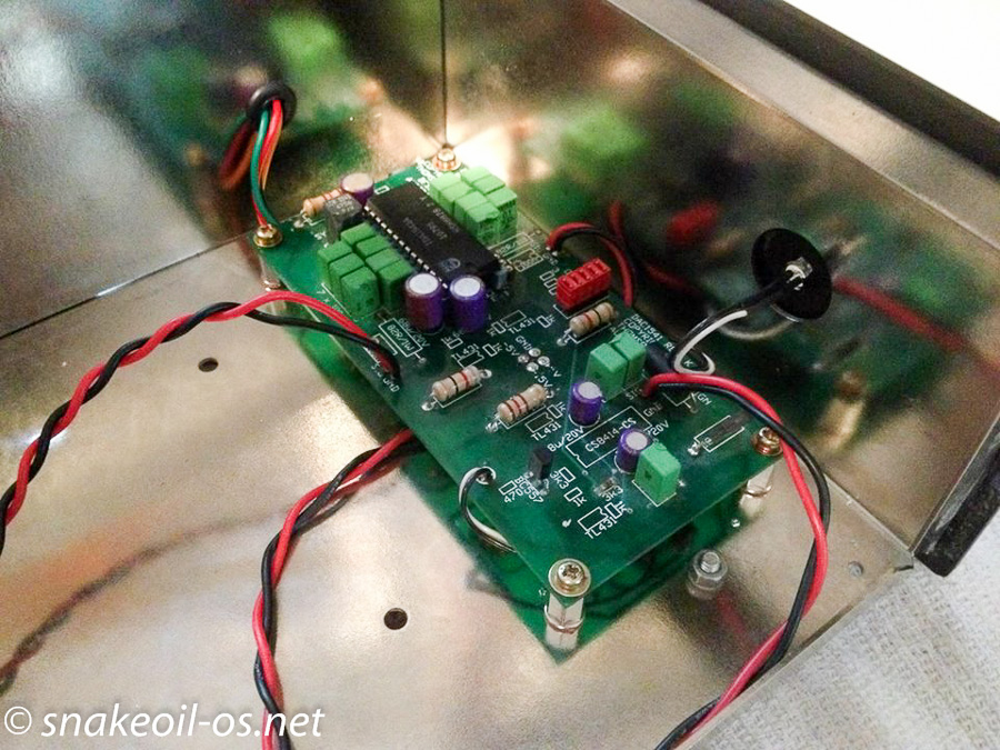
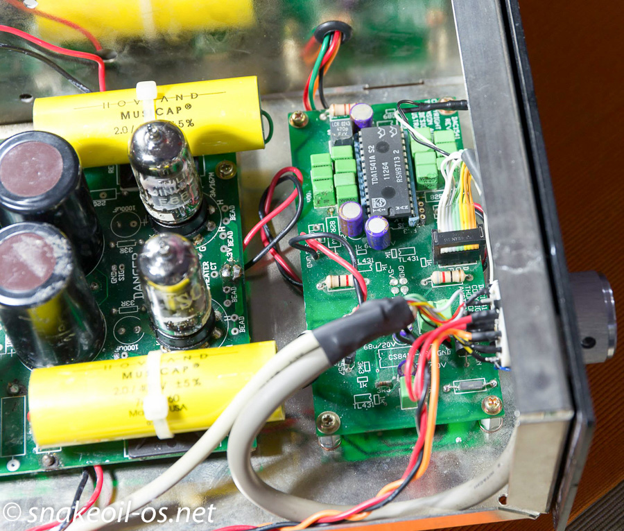
Here you see the DAC board, picture shown is a TDA1541A chip. The black/white wire is a S/PDIF lock LED. Pay attention to the 5 set of red jumpers near the DAC chip (next to a resistor) as I will talk more about them later.
The valve output stage and it's caps are now fitted back in, space is getting tighter and tighter!
The final assembly.
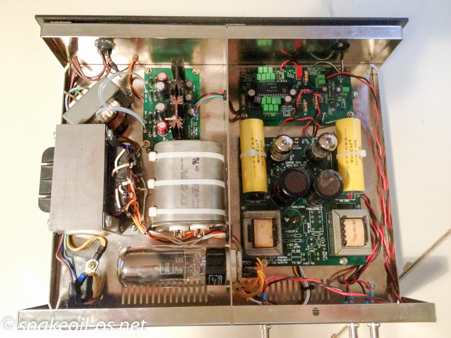
Don did an excellent work cleaning up the wiring, and reassemble the DAC. There are no circuit diagrams for this DAC, and a lot of time must have been spent trying to reverse engineer the layout. Kudos Don!
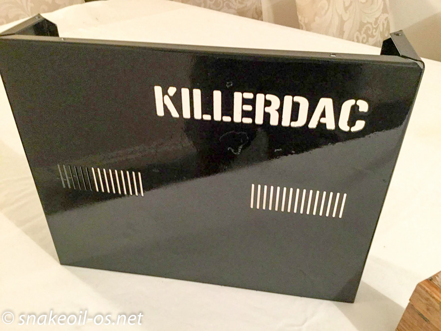
It's time to pretty up the looks now that the internals are done. Here you can see the original black case. It's dull and boring. The biggest problem with this cover is there is not enough ventilation to vent the heat from the rectifier tube. In summer the heat builds up and the DAC starts emitting a lot of heat induced noise which plays out to the system. I had to remove the cover whenever I used the DAC, a silly thing to do as this is a live 240V unit. The solution is to add more ventilation holes to the cover, and what better than to do that with words? Here is the cutting in action, with Don's CNC machine.
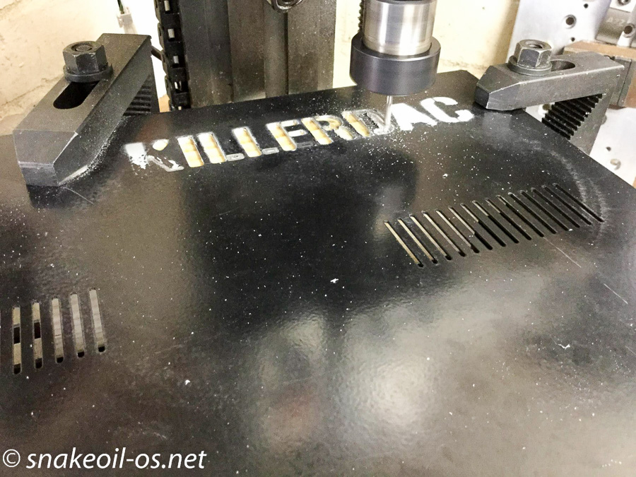
Starting to look better already! So the words sit on top of the rectifier tube, coupled with the existing vent holes from the bottom, the problem of heat induced noises is now solved.
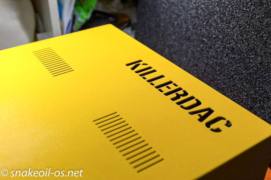
Having lived with this black box for a while, I wanted a radical look to my KillerDAC - black is so boring. Don offered to powder coat it for me, and I settled on Yellow (my last name in my native tongue)
And this was the KillerDAC after the first re-work. Still using the stock black face plate. The LED was so bright I had to cover it with bluetac.
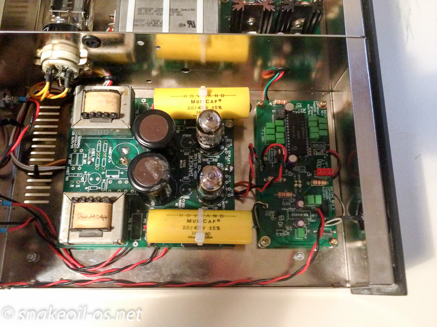
Remember the red jumpers a while back? Don figured we can use that to add additional inputs. He managed to find a 10 pin header that fit the existing pins, and it's time for the second iteration. In this picture you can see the Taiwan double crown. This chip sounds less warm then the other TDA1541A chip I have, but has slightly better focused imaging and has a "brighter" presentation.
The wire loom goes to a rotary switch (bottom right), where it's a matter of selecting different inputs by simply rotating it. The beauty of this setup is it is possible to from I2S to S/PDIF without fiddling with messy jumpers, when the DAC is powered on. This is a feature other KillerDAC implementations don't have.
The tubes are Phillips SQ which have now gone bad. Wish I can find another pair for a good price.
A picture showing the rear of the KillerDAC with the additional inputs. Because this is a red book DAC, the I2S signal is simple (bit clock, left/right clock and data). I am using normal Ethernet cables for the I2S physical link and that is why you see the Neutrik Ethernet connector. I have tried a 1.5 m long Ethernet cable and the audio still plays perfectly fine. Testament to Don's work because current wisdom is I2S cables have to be as short as possible.
So what you see are two S/PDIF inputs, 1 I2S input and finally the left/right analogue outputs.
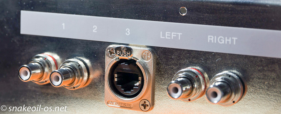
And this is the current iteration of the KillerDAC today, with a nice looking bamboo fascia. The next step of the KillerDAC evolution is to remove 1 S/PDIF and replace it with a balanced I2S (that's why you see I2S A and I2S B). And Don will modify a Juli@ for me and give me balanced I2S out straight from my computer rig (bypassing USB and my digital interface).
So there you have it. Hopefully a small glimpse into my system will give you a general idea how Snakeoil comes to be.
Follow The Music, Follow Snakeoil.
Related News

Problem With Accuphase DC-37 USB
So my Accuphase DC-37's USB input was damaged a while back.
Add new comment